
As a reliable CAN Bus PLC supplier, I understand the importance of the CAN Bus wake - up mechanism in Programmable Logic Controllers (PLCs). This mechanism is crucial for energy - efficient operation and timely system responses. In this blog, I'll guide you through the process of configuring the CAN Bus wake - up mechanism in a PLC.
Understanding the CAN Bus and Its Wake - up Mechanism
The Controller Area Network (CAN) Bus is a robust serial communication protocol widely used in industrial automation, automotive, and other fields. It allows multiple nodes to communicate with each other on a shared bus. The CAN Bus wake - up mechanism is designed to enable a PLC to transition from a low - power or sleep mode to an active mode when a specific event occurs on the CAN network.
In a typical industrial scenario, PLCs may need to conserve energy during periods of inactivity. However, they must be ready to respond immediately when there is new data or a control command on the CAN Bus. The wake - up mechanism ensures that the PLC can quickly resume normal operation and process incoming messages.
Prerequisites for Configuration
Before you start configuring the CAN Bus wake - up mechanism in your PLC, there are several prerequisites that you need to meet:
- Hardware Compatibility: Ensure that your PLC has a CAN Bus interface and supports the wake - up feature. Different PLC models may have different hardware capabilities, so refer to the product documentation of your CAN Bus PLC for detailed information.
- CAN Bus Network Setup: The CAN Bus network should be properly configured, including setting the correct baud rate, termination resistors, and node addresses. Incorrect network settings can lead to communication errors and affect the wake - up mechanism.
- Software Environment: You need to have the appropriate programming software installed on your computer. This software is used to configure the PLC, including setting up the CAN Bus wake - up parameters.
Step - by - Step Configuration Process
Step 1: Access the PLC Configuration Interface
First, connect your computer to the PLC using a suitable communication cable, such as an Ethernet cable or a serial cable. Launch the programming software and establish a connection to the PLC. Once connected, access the configuration interface of the PLC.
Step 2: Enable the CAN Bus Interface
In the PLC configuration interface, navigate to the section related to communication interfaces. Locate the CAN Bus interface and enable it. You may need to set the baud rate, which determines the speed of data transmission on the CAN Bus. Common baud rates include 125 kbps, 250 kbps, and 500 kbps. Select the baud rate that is compatible with your CAN Bus network.
Step 3: Configure the Wake - up Conditions
The wake - up conditions define the events that will trigger the PLC to wake up from the sleep mode. There are several types of wake - up conditions that you can configure:
- Message - Based Wake - up: You can set the PLC to wake up when it receives a specific CAN message. This is useful when you want the PLC to respond to a particular control command or data packet. In the configuration interface, specify the CAN message ID or a range of message IDs that will trigger the wake - up.
- Bus Activity Wake - up: The PLC can be configured to wake up when there is any activity on the CAN Bus. This includes the transmission or reception of any CAN message. This type of wake - up condition is suitable for applications where you need the PLC to monitor the network continuously.
- Timer - Based Wake - up: You can also set a timer to wake up the PLC at regular intervals. This is useful for applications where the PLC needs to perform periodic tasks, such as data logging or status checks. In the configuration interface, set the timer interval in milliseconds or seconds.
Step 4: Set the Sleep Mode Parameters
After configuring the wake - up conditions, you need to set the sleep mode parameters. This includes specifying the conditions under which the PLC will enter the sleep mode. For example, you can set the PLC to enter the sleep mode after a certain period of inactivity on the CAN Bus.
Step 5: Save and Download the Configuration
Once you have completed the configuration of the CAN Bus wake - up mechanism, save the configuration in the programming software. Then, download the configuration to the PLC. The PLC will restart and apply the new configuration.
Testing the Wake - up Mechanism
After downloading the configuration to the PLC, it's important to test the wake - up mechanism to ensure that it works correctly. You can use a CAN Bus analyzer or a test device to send test messages on the CAN Bus and verify that the PLC wakes up as expected.
- Message - Based Wake - up Test: Send a test message with the specified CAN message ID on the CAN Bus. Check if the PLC wakes up and starts processing the message.
- Bus Activity Wake - up Test: Send any CAN message on the CAN Bus and verify that the PLC wakes up.
- Timer - Based Wake - up Test: Wait for the timer interval to expire and check if the PLC wakes up at the specified time.
Troubleshooting
If the CAN Bus wake - up mechanism does not work as expected, you can follow these troubleshooting steps:
- Check the Configuration: Review the configuration settings in the programming software to ensure that they are correct. Make sure that the wake - up conditions, sleep mode parameters, and CAN Bus settings are properly configured.
- Verify the Hardware Connection: Check the physical connection between the PLC and the CAN Bus network. Ensure that the cables are properly connected and that the termination resistors are installed correctly.
- Check for Interference: CAN Bus communication can be affected by electromagnetic interference. Make sure that the CAN Bus cables are shielded and that there are no sources of interference near the PLC or the CAN Bus network.
- Update the Firmware: Check if there are any firmware updates available for your PLC. Updating the firmware can sometimes fix bugs and improve the performance of the CAN Bus wake - up mechanism.
Comparison with Other Bus Technologies
While the CAN Bus is a popular choice for many applications, there are other bus technologies available, such as the EtherCAT Bus PLC and Compact Mini PLC.
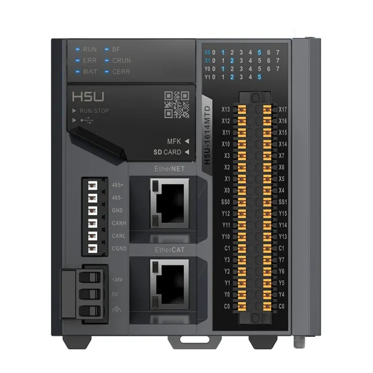
- EtherCAT Bus PLC: EtherCAT is a high - speed Ethernet - based fieldbus system. It offers faster communication speeds and higher bandwidth compared to the CAN Bus. However, the wake - up mechanism in an EtherCAT Bus PLC may be more complex due to the higher - level communication protocols involved.
- Compact Mini PLC: Compact Mini PLCs are designed for small - scale applications. They may have limited communication capabilities compared to full - sized CAN Bus PLCs. However, they are more cost - effective and easier to install in space - constrained environments.
Conclusion
Configuring the CAN Bus wake - up mechanism in a PLC is an important step in ensuring energy - efficient operation and timely system responses. By following the steps outlined in this blog, you can successfully configure the wake - up mechanism in your CAN Bus PLC.
If you have any questions about the CAN Bus wake - up mechanism or need assistance with PLC configuration, please feel free to contact us. We are here to provide you with professional technical support and help you find the best solutions for your industrial automation needs. Whether you are looking to optimize energy consumption or improve system performance, our team of experts can guide you through the process. Contact us today to start the procurement and negotiation process and take your industrial automation to the next level.
References
- CAN in Automation (CiA) - CANopen Specification
- PLC Manufacturer's Product Documentation
- Industrial Automation Handbook