
Setting up a CAN Bus network for a water treatment PLC system is a crucial step in ensuring efficient and reliable operation of the entire water treatment process. As a CAN Bus PLC supplier, I have extensive experience in helping customers establish such networks. In this blog post, I will guide you through the process of setting up a CAN Bus network for a water treatment PLC system, from understanding the basics to the final implementation.
Understanding CAN Bus and Its Benefits in Water Treatment PLC Systems
CAN Bus, or Controller Area Network Bus, is a robust serial communication protocol designed for real - time applications. It was initially developed for the automotive industry but has found wide applications in industrial automation, including water treatment systems.
One of the main advantages of using CAN Bus in a water treatment PLC system is its high reliability. CAN Bus uses a differential signaling technique, which makes it less susceptible to electromagnetic interference. This is particularly important in water treatment plants where there are many electrical devices operating simultaneously.
Another benefit is its multi - master capability. In a water treatment system, multiple PLCs may need to communicate with each other to control different aspects of the process, such as filtration, disinfection, and pumping. CAN Bus allows multiple nodes to communicate on the same network without the need for a central controller, providing greater flexibility.
CAN Bus also offers high data transfer rates, which are sufficient for most water treatment applications. It can support data rates up to 1 Mbps, allowing for quick and efficient communication between PLCs and other devices.
Components Required for a CAN Bus Network in Water Treatment
Before setting up a CAN Bus network for a water treatment PLC system, you need to gather the necessary components.
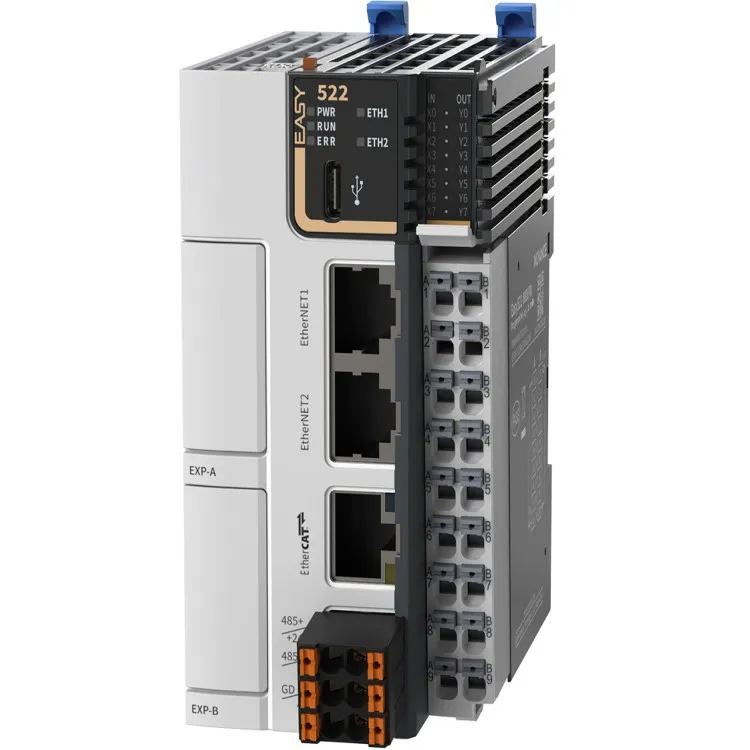
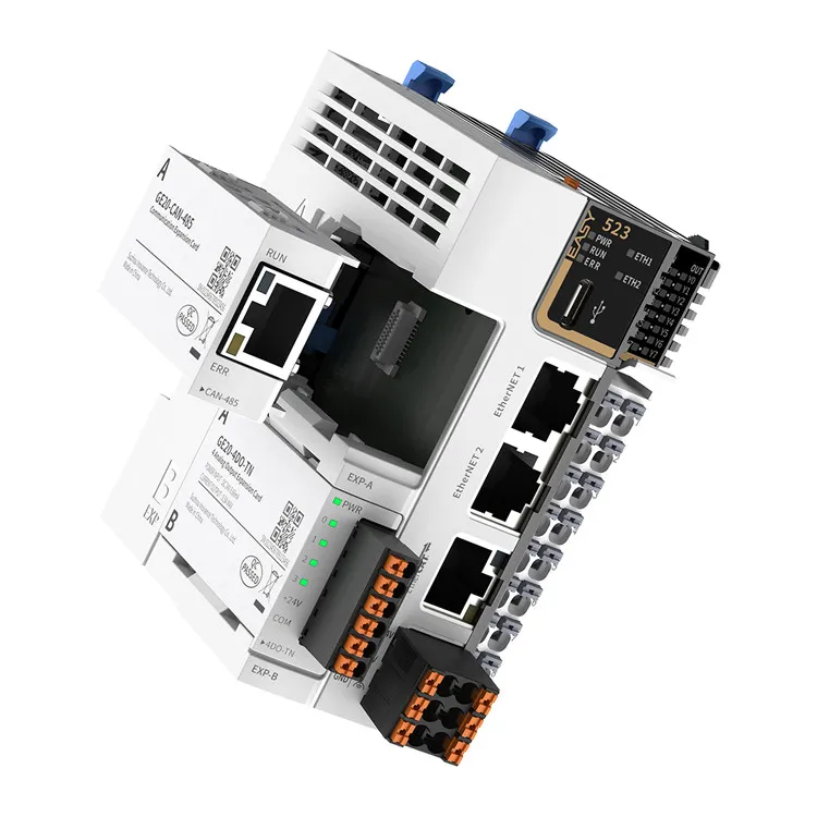
CAN Bus PLC
The CAN Bus PLC is the heart of the network. It is responsible for controlling the water treatment process and communicating with other devices on the CAN Bus. Our CAN Bus PLCs are designed with high - performance processors and advanced communication modules to ensure stable and efficient operation.
CAN Transceivers
CAN transceivers are used to convert the digital signals from the PLC into differential signals suitable for transmission over the CAN Bus. They also receive incoming differential signals and convert them back into digital signals for the PLC. Make sure to choose transceivers that are compatible with your CAN Bus PLC and can operate in the environmental conditions of your water treatment plant.
Termination Resistors
Termination resistors are essential for a CAN Bus network. They are placed at each end of the bus to prevent signal reflections, which can cause communication errors. The standard value for termination resistors in a CAN Bus network is 120 ohms.
CAN Bus Cables
High - quality CAN Bus cables are required to ensure reliable communication. The cables should have good shielding to protect against electromagnetic interference. Twisted - pair cables are commonly used for CAN Bus networks.
Step - by - Step Guide to Setting Up a CAN Bus Network
Step 1: Design the Network Topology
The first step in setting up a CAN Bus network is to design the network topology. The most common topology for a CAN Bus network is the linear bus topology, where all devices are connected to a single cable. This topology is simple and easy to install, making it suitable for most water treatment applications.
When designing the topology, consider the physical layout of your water treatment plant and the location of the PLCs and other devices. Make sure the cables are routed away from sources of electromagnetic interference, such as large motors and transformers.
Step 2: Install the CAN Bus PLCs and Other Devices
Once the network topology is designed, install the CAN Bus PLCs and other devices at their designated locations. Make sure to follow the manufacturer's installation instructions carefully. Connect the CAN transceivers to the PLCs and other devices, and ensure that the connections are secure.
Step 3: Connect the CAN Bus Cables
Connect the CAN Bus cables between the devices according to the network topology. Use appropriate cable connectors and ensure that the cables are properly shielded. Install the termination resistors at each end of the bus.
Step 4: Configure the CAN Bus PLCs
After the hardware installation is complete, it's time to configure the CAN Bus PLCs. This involves setting up the communication parameters, such as the baud rate, message identifiers, and error handling. Our CAN Bus PLCs come with user - friendly configuration software that makes it easy to configure the devices.
Step 5: Test the Network
Once the PLCs are configured, test the CAN Bus network to ensure that it is working properly. You can use diagnostic tools to check the communication between the devices and to detect any errors. If there are any issues, troubleshoot the network by checking the hardware connections, the configuration settings, and the termination resistors.
Comparison with Other Bus Systems
While CAN Bus is a popular choice for water treatment PLC systems, there are other bus systems available, such as EtherCAT Bus PLC and Compact Mini PLC.
EtherCAT Bus PLC offers higher data transfer rates and lower latency compared to CAN Bus. It is suitable for applications that require high - speed real - time communication. However, it is more complex to set up and may require more expensive hardware.
Compact Mini PLCs are small and cost - effective, but they may have limited communication capabilities compared to CAN Bus PLCs. They are more suitable for small - scale water treatment applications with simple control requirements.
Conclusion
Setting up a CAN Bus network for a water treatment PLC system requires careful planning and proper implementation. By understanding the components required, following the step - by - step guide, and considering the comparison with other bus systems, you can ensure a reliable and efficient CAN Bus network for your water treatment plant.
As a CAN Bus PLC supplier, we are committed to providing high - quality products and professional technical support. If you are interested in setting up a CAN Bus network for your water treatment PLC system or have any questions, please feel free to contact us for further information and procurement discussions.
References
- Bosch, "Controller Area Network (CAN) Specification Version 2.0," Bosch, 1991.
- ISO 11898 - 1:2015, "Road vehicles -- Controller area network (CAN) -- Part 1: Data link layer and physical signalling."